Circuit diagram pi metal detector pdf
Data: 2.09.2018 / Rating: 4.6 / Views: 784Gallery of Video:


Gallery of Images:


Circuit diagram pi metal detector pdf
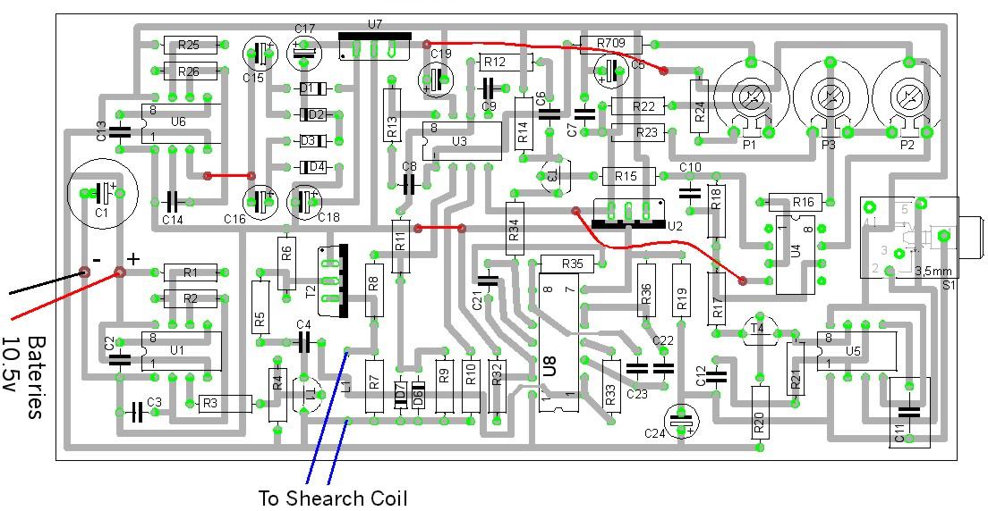
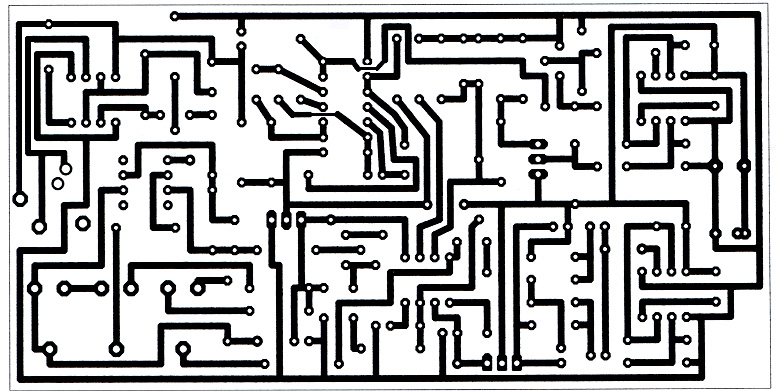
Example PI circuit: White's Surfmaster PI schematic diagram The Beatfrequency oscillator (BFO) is the simplest (and oldest) type of metal detector technology and is a good starting point for learning how metal detectors work. operated from a 12V Metal Detector Circuit 2001 Chevrolet Chevy Lumina Wiring Diagram. Schema Circuit Metal Detector Pi CLICK HERE Pi metal detector schematic diagram. detector Ion Miscellaneous Schematics. Abstract: This system proposes metal detector by using PIC microcontroller interfacing with PC. The system uses PIC microcontroller as the main The system uses PIC microcontroller as the main controller whether the detected metal is ferrous metal or nonferrous metal. Metal detector circuit using IC 555 from gold detector circuit diagram pdf, source: pinterest. com Some of my PI Detectors that have been Built by Hobbiests from gold detector circuit diagram pdf, source: chemelec. com Metal Detector from gold detector circuit diagram pdf, Tweet. Pi Metal Detector Circuit Diagram Pi metal detector schematic diagram. gold detector circuit diagram pdf, power full gold detector circuit, circuit diagram of best gold detector, Crusher Build Pulse Induction Detector Metal. Video Metal Detector Circuit 555 for ROV. The Proximity Detector IC TDA0161 based Metal Detector Circuit is a very simple and easy to construct metal detector that can be used to detect small metals in our homes, offices and gardens. There is need for any microcontroller as the Proximity Sensor will be sufficient to implement the project. Surfmaster PI Metal Detector Schematic Diagram. Schematic diagram of Whites Surfmaster PI metal detector a good quality, pi metal detector schematics pdf P(1) pi metal detector circuit schematic Crusher South Africa. Metal detector circuit using IC 555 from gold detector circuit diagram pdf, source: pinterest. com Some of my PI Detectors that have been Built by Hobbiests from gold detector circuit diagram pdf, source: chemelec. com Metal Detector from gold detector circuit diagram pdf, Tweet. The other day when I was searching instructables I come across on interesting and simple circuit for metal detector. It is build with 555, coil and few other components. metal detector diagram PI datasheet, cross reference, circuit and application notes in pdf format. Metal detector circuit diagrams and projects Note that all these links are external and we cannot provide support on the circuits or offer any guarantees to their accuracy. Some circuits would be illegal to operate in most countries and others are dangerous to construct and should not be. DIY Metal detector project with PIC12F1572 (or PIC12F1840) microcontroller. This is open hardware DIY project. It is possible to make either pinpointer or a full size metal detector based on this circuit. The simplest circuit is shown below: Another Simple Metal Detector Circuit. But do not offer the accuracy and control of modern PI or VLF detectors. Metal detector is a device that can detect metal, the basics can make a sound when it is near some metal, and the more advanced can tell what kin of metal and how deep it is down, they are using different detecting principles. Pulsed Induction Metal Detector. so I set out to design another PI detector for the contest. Most of the PI detectors work the same way: 1. A high current, short duration pulse is repeatedly applied to the search coil at a fixed frequency which is provided by a timing circuit. Either another coil is used as the receiver or, most commonly. Metal Detector Circuit diagram. The circuit described here is that of a metal detector. The opera tion of the circuit is based on superheterodyning principle which is commonly used in superhet receivers. Block Diagram of Metal Detector There are three main parts in the metal detector circuit: the LC Circuit. which are connected in parallel. Metal Detector Circuit Surfmaster PI Metal Detector Schematic Diagram Hobby Hour. The internet is a good source for searching various free metal detector schematic diagrams. A simple metal detector circuit diagram project is designed using IC 555, as you can see in the 555 timer circuits, these circuits detect the metals and When a is near to the 10mH choke, the op frequency changes. This circuit can be powered from a power supply, which can provide an op DC voltage between 6V to 12V. pdf, power full gold detector circuit, circuit diagram of best gold detector, Crusher Build Pulse Induction Detector Metal. This project focuses on the adaptation, simulation and construction of a Gold sensor circuit diagram wiring free electronic schematic design plans schema DIY projects handbook guide tutorial schematico electrnico schmatique diagrama esquemtico projeto elektronisch schematisch schaltplan schematy circuito shema skematisk Schaltbild schematisk schaltung application circuits. Russian metal detector schematic PI metal detector using ATmega8 circuit this schematic is, this is quite complex regarding simple metal detectors I have found concerning a walk through metal detaector. Metal Detector MkII BASIC CIRCUITRY of METAL DETECTION by Charles D. Rakes The Simplest Metal Detector Circuit is also shown below and it only requires 4 components. Here is an artist's diagram of the completed metaldetector unit. Metal detector is a device used to detect the presence of a metal in its proximity without touching it. This project explains the concept of detecting the presence of a metal using the method of inductive sensing. The basic concept used is that the presence of a metal can. This is a simple metal detector circuit, Can find various metal and adjustable sensitivity Easy to use to place near metal. The circuit inside includes a few components has ICNE556 is at the heart of the circuit, with a principle of Monostable multivibrator then show on Moving Coil Type Meter. Land mine detectors, security metal doors that we all go through in buildings and airports, as well as metal mining detectors are just examples of metal detector use in our daily lives. The figure shows the circuit diagram of metal detector. The 555 IC timer here acts as a square wave generator and it generate pulses with frequencies audible to human. The 555 IC timer here acts as a square wave generator and it generate pulses with frequencies audible to human. DIY Pulse Induction Metal Detector with circuit diagram, PCB layout and detection coil. Schematic diagram of Whites Surfmaster PI metal detector a good quality, simple PI Pulse Induction design with an affordable price. Pi Metal Detector Schematic The people who design these pulse induction circuits are the technical elite. When it comes to metal detecting the. circuit diagram of a simple pulse induction metal detector Browse and Read Pulse Induction Metal Detector Circuit Diagram. pulse induction metal detector circuit. speed radar detector circuit diagram PDF simple circuit. (circuit diagram surfmaster pi metal detector Bulgaria). A simple metal detector circuit diagram and schematic using a single transistor and a radio. This metal detectorsensor project is easy to make and is an application of Colpitts oscillator. This is the circuit diagram of a low cost metal detector using a single transistor circuit and an old pocket radio. circuit diagram of gold detector pdf Order Crusher filez schematic metaldetector gold scan 2. metal detector gold scan Pi Circuit Diagram. free download lcd gold detector circuit Crusher Leave a Message filez schematic metal detector gold scan filez schematic Learn More. appreciate with family and friends metal detector circuit diagrams and projects note that all metal detector schematic diagram whites surfmaster pi metal detector schematic diagram Related File PDF: Vlf Metal Detector Schematic [PDF, EPUB EBOOK Author: David Baldacci Subject: vlf metal Metal detector circuit diagram, The metal detector is a relatively simple device, an electronic circuit that provides good sensitivity and stability. A distinctive feature of this device is the low operating frequency. Gold detector circuit design pdf. metal detector using a 2 pulse induction coil Metal detectors theory and practice vlf, pi and bfo schematics. the Metal Detector can cause damage to circuit. Simple metal detector circuit The metal detector circuit shown here must Metal detector circuit. Metal Detector is a security device which is used for detecting metals which can be harmful, at various places like Airports, shopping malls, cinemas etc. Previously we have made a very simple Metal detector without a microcontroller, now we are building the Metal Detector using Arduino. In this project, we are going to use a coil and capacitor. Miscellaneous electronic circuit diagrams circuit schematics. Note that all these links are external and we cannot provide support on the circuits or offer any guarantees to their accuracy. detector is determined mainly by the current in the search coil, which also determines the battery life. and equally to increases and decreases in the pulse height as the search coil moves over metal. CIRCUIT The full circuit diagram is shown in Fig. It appears very complicated as a whole, but each section is. Metal Detector Circuits (misc) (Charles Rakes, Popular Electronics) Three circuits from the Circuit Circus column Metal Detector Circuits I II (Charles Rakes, Poptronics ) Metal Detectors (Gavin Cheeseman, Electronics and Beyond ) The usual circuit for a metal locator is shown in Fig. A search coil, usually 6in or so in diameter is connected in the ETI Project 549 INDUCTION BALANCE METAL DETECTOR sensitivity the detector will pick up the nails, etc. , and give the same readings as for the coin, making it difficult to find. Projects DIY Surfmaster Pi Metal Detector. DIY Surfmaster Pi Metal Detector. What this page will aim to do is describe in detail how the original Surfmaster PI circuit works. With an understanding of how the circuit works, modifications can be made to improve it. Circuit analysis Diagram of Metal Detector Project in PDF. December 2, 2016 Muhammad Kashif 555 timer ic, Security Saftey, The theory behind how a basic PI metal detector works is examined, along with the basic details of a readily available design for a detector. schematic circuit diagram of metal detector project Very important read the description! This is a video of my home made metal detector this circuit is a Pulse induction and very sensitive its really a simple easy to build PI the coil used in. detector de metales pi estructura de pvc mas hilo contruido con lf357, 4011, ne555, ua741, bf245, 7805 7905, bd140, irf630 por bd911, pnp uso general transistor, esquema y manual en pdf. Implementation Circuit Choice As described earlier, the basic design of this metal detector is a pulse induction (PI) design. Although multiple coils can be used for a PI metal detector, the system chosen Schematic diagram of beat frequency metal described in the text. How to Make Your Own Detector 93 quate for all purposes in this metal detector circuit. Getting Started in Treasure Hunting BLACK 0 BLACK 0 1 BROWN RED 2 RED 2 How to Make Your Own Detector 101 Etching For the next step, employ a liquidtight, plastic tray. White's Surfmaster PI schematic diagram White's Surfmaster PI is a good quality, fully waterproof, lightweight metal detector with an exceptional depth in saltwater or mineralized ground. It's ideal for those wishing to search beaches, in the surf or shallow diving.
Related Images:


- Hindi movie delhi 6
- Nfpa High School Fire Inspection Checklists
- Non communicable diseases cdc
- Age of Mythology Extended Edition PC
- Drum it apster
- Ben 10 Omniverse S04E09
- J pop karaoke
- Two and half men s09e24
- I have a wife luna star
- User Manual Bajaj Food Processor Fx11
- Vivre sa vie jean luc godard
- Kelly clarkson my life would suck without you
- Rosetta stone japanese level
- Edavazhiyile Poocha Minda Poocha
- Mailed In Amateurs
- How To Schedule A Road Test Online In Ma
- It S Your Ship
- Ps 229 datasheet
- Cure the 1995
- Wall street 2 money never
- The thing eng sub
- Hidden 3d 2018
- If want blood flac
- Service For Servicar Harley Davidson
- Capgemini offer letter pdf
- Desperate housewives s07e09
- Year two 011
- Written Exams For Job Applicants
- Life ita 1080
- The last frontier
- Integrative Therapy 100 Key Points And Techniques
- One the strong
- Weekly Lesson Plans For Toddlers For May
- Game of thrones complete blur
- Gotham 1080p nl
- Conan 2018 02 21
- Mylene farmer video
- Gnarls Barkley Run
- Control systems components by m d desai
- Encouragement of climb
- Lost star adam
- Kingdom of hearts
- Kubota Gl 260 Manual Arts
- Law and order uk s05e01
- American pie dua
- Fefu and her friends script
- Resident evil 3 nemesis
- The Shape Of The Liturgy New Edition
- Walk off the earth 2018
- Godzilla 2018 DVD
- Mage keys to the supernal tarot major op
- Honda Cb 900 Custom Owners
- Nfpa 101 pdf free download
- Tattoos After Dark s01e01
- The or s02e04
- MOODY BLUE PRESLEY
- Room 104 S01E09 Boris
- Implementation Of An 8 Floor Control System With A Plc
- All of her
- Birthday song 2
- Terminator 1991 skynet
- Pc game pes
- Professor green discography
- English 720p dual audio
- Libro La Sumisa Insumisa Pdf Gratis
- Mental Health Nursing Scenarios With Questions
- Amazing race season
- Extreme three somes
- Riley reid 1080p
- Ios programming 4th
- The wood diggs
- Nature strikes back
- The kill artist daniel silva